Introduction:
As we know that every electronic gadgets requires power source to run power it. In this article we will learn how a simple 5V 1A power supply can be designed.
Where to start?
It is not that much complicated to design a basic DC power supply circuit which will run around 5V 1A.
Hardware components required:
- Step down transformer -> 12V 1A
- PN diodes -> 1N4001
- Capacitor -> 1000uf/25V, 0.1uf
- LED -> RED colour
- voltage regulator -> 7805
- Fuse -> 1A 250V
Principle of operation:
“ The principle of operation behind this, is converting the bipolar signal to unipolar signal”.
The design block diagram as follows.
Fig 1: block diagram of simple DC power supply
Step down transformer:
By stepping down the 230V ac to the minimum ac voltages the designing can made easy. In this case we are using the 6V 1A step down transformer.
Rectifier:
This will change the change the shape of the bipolar signal to the unipolar AC signal (pulsating DC signal) for better efficiency and ripple factor we use full wave bridge rectifier. Using four diodes as shown below.
“Note: while designing the rectifier using diodes consider the barrier voltage drop at each resistor this will drop the output voltage to the Filter circuit.”
There are ready made rectifier ICs are available with different packages, you can choose according to your design. While choosing consider the Wattage rating of the IC. In this case 5W is suggestable.
Filter circuit:
This is required because of the pulsating nature of the source signal alter the device behaviour. This is the DC form by adding this filter circuit here we have different types of filter circuits like C-filter, RC-filter, Pi-filter.
For simple design C-filter is used. Typically the C-filter have the capacitor in parallel to the +ve voltage and 0V terminals. Here we use electrolytic capacitor. This can be termed as reservoir capacitor. The calculations required for the selection of this capacitor is as follows.
Whereas,
I_max è maximum current required by load;
T_discharge è Time period of input sine wave or AC signal (60Hz typically);
T_discharge for halfwave rectifier = 16.6ms
T_discharge for fullwave rectifier = 8.3ms
V_before discharge -> V_max;
V_after discharge -> V_min fed to the voltage regulator;
The minimum value of the capacitor allows to limit the current required to load.
“Note: to prevent the over voltage of the electrolytic capacitor the maximum voltage rating of the capacitor is twice the value of the V_max.”
We are writing the theoretical calculations for this design so it is recommended to use 1000uf capacitor of 25V.
Voltage regulator:
These are the kind of constant DC voltage output devices that is, it will maintain the steady voltage on with respective to input.
There are two kinds of voltage regulators available they are,
- Positive voltage regulators -> 78XX
- Negative voltage regulators -> 79XX
The last two digits represent the output voltage.
“Note: the input voltage must be greater than the rated voltage regulator value.”
“Note: It is important that while using voltage regulator it is really important to maintain the minimum voltage which is provided in the IC datasheet.”
Circuit diagram:
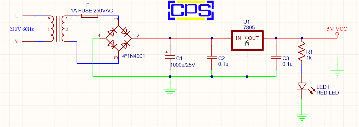
Fig 2: circuit diagram